Hardware
The reference build uses a Raspberry Pi Pico driving 8 RGB buttons plus START/SELECT LEDs. It is the best-supported hardware; for other boards, see External LED boards.
The component list
The reference kit, fully solder-free (full detail in resources\setup\kits\default.json):
| Component | Qty | Role |
|---|---|---|
| Raspberry Pi Pico H | 1 | LED controller (the H version avoids soldering) |
| GPIO breakout board (Freenove-style) | 1 | Solder-free access to GPIOs and 3V3 |
| 4-wire RGB arcade buttons (SJ@JX / SAJAX) | 8 | Main buttons, full RGB (3 GPIOs each) |
| RGB buttons used in fixed color | 2 | START and SELECT (only one color wire connected) |
| Dupont → XH2.54 4P connectors | 10 | One per button, solder-free connection |
| Dupont 2.54 mm block for the common | 1 | Distributes 3V3(OUT) to the 10 buttons |
| Micro-USB data cable | 1 | Communication + power (not a charge-only cable!) |
| Arcade joystick + USB input encoder | 1+1 | The game inputs - any board you like (Zero Delay, DragonRise, I-PAC…), LedManager never touches them |
Also recommended: spare Dupont wires, labels to mark B1–B8 and the color channels, cable ties; optionally a multimeter and an external 5 V supply if USB is not enough at full brightness.
Wiring
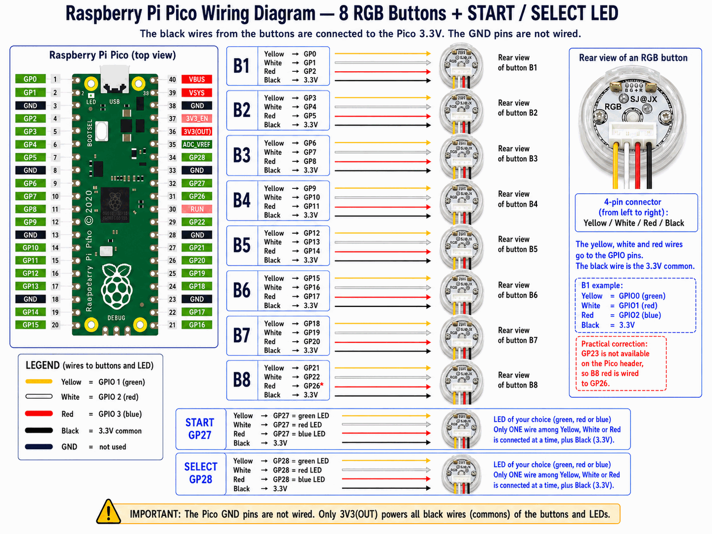
Key points of the diagram:
- Each RGB button uses 3 GPIOs (yellow, white, red wires): B1 = GP0/GP1/GP2, B2 = GP3/GP4/GP5, and so on.
- The black wire of each button is the common, connected to the Pico's 3.3V - GND pins are not wired.
- START uses GP27 and SELECT GP28, with a simple LED (only one of the three color wires connected, your choice).
- Special case: GP23 is not available on the connector, so B8's red is wired to GP26.
Important
Only 3V3(OUT) powers the buttons' and LEDs' common wires. Do not wire the Pico's GND pins to the buttons.
The standard arrangement recommended for RetroBat
Physically place your buttons following this arrangement - it is the one the Data Pack's per-game panels expect:
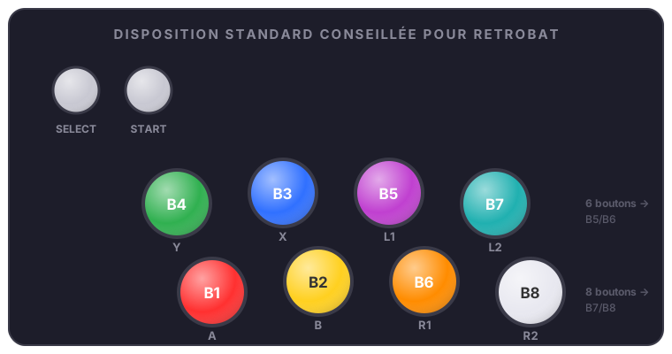
SELECT   START

 B4·Y    B3·X    B5·L1    B7·L2
 B1·A    B2·B    B6·R1    B8·R2
Its strength: it stays functional from 2 to 8 buttons without rewiring, because each button keeps its identity. A 2-button panel = B1 B2; with 4 buttons you add the top row B4 B3; with 6 you add the B5/B6 column (L1/R1); with 8 the B7/B8 column (L2/R2). Growing your panel never forces you to move an existing button, and per-game colors always land in the right place.
SELECT then START sit at the top-left of the panel. This arrangement is described in resources\setup\layouts\retrobat_standard.json - it is what the virtual panel in LedManagerSetup.exe displays.
The Setup Manager during a game
The virtual panel deliberately runs at low priority and batches its refreshes to stay as light as possible. A slight in-game slowdown is still possible while the window is open during a game - that is normal: it is a tuning tool, close it for serious play.
Already automated - the following sections are for advanced users
Flashing the firmware, checking the Pico and describing your panel are fully handled by the assistant in LedManagerSetup.exe: it deploys the firmware, detects and tests the Pico, then writes the panel description for you. What follows is only useful for troubleshooting or to understand what happens under the hood - not required for a normal install.
Flashing the firmware
The Pico firmware ships in the plugin's fw\ folder. To deploy it:
powershell -NoProfile -ExecutionPolicy RemoteSigned -File tools\deploy-pico-fw.ps1
The script copies main.py, profiles_db.py and hardware_profiles.py onto the Pico (MicroPython required). If the Pico misbehaves, tools\reset-pico.ps1 forces a clean restart.
Checking the Pico
The firmware answers two diagnostic commands over serial (115200 bauds):
VERSION  →  VERSION DYNAMIC_PANEL_ADDR 2026.06.20
CAPS     →  CAPS PING,INIT,PTR,BUS,HW,GPIO,SLOT,SLOTPWM,...
It is the fastest way to confirm the firmware is present and up to date before blaming the configuration.
Describing your panel
Once the hardware is wired, describe it in plain words in PicoCommandSender.ini - button count, LED type, GPIOs used:
[Hardware:P1]
PanelButtons=8
PanelButtonType=RGBLED
Start=LED
Select=LED

[GPIO:P1]
B1=0,1,2
B2=3,4,5
START=27
SELECT=28
Available types: NONE (absent), LED (simple ON/OFF, 1 GPIO), RGBLED (3 GPIOs), ADDRLED (addressable WS2812/NeoPixel). The sender handles all firmware initialization - you never need to know an internal profile name.
The rest of the configuration (routing, colors, serial port) is covered in Configuration.